02. Hardware List

Hardware List
To perform this lab, you will need to get a few pieces of hardware. We have partnered with our friends at Sparkfun to put together a kit so you can buy all the pieces you need in one, easy stop! Follow the link to grab yourself one!
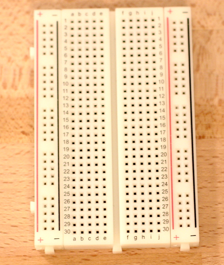
Breadboard
This project will only require a small breadboard. You’ll need a solderless breadboard similar to this one for this lab so that you can reuse the components. In a breadboard like the one shown below, the + and - “rails” are internally connected. The interior numbered groups are also internally connected.
Additional resources:
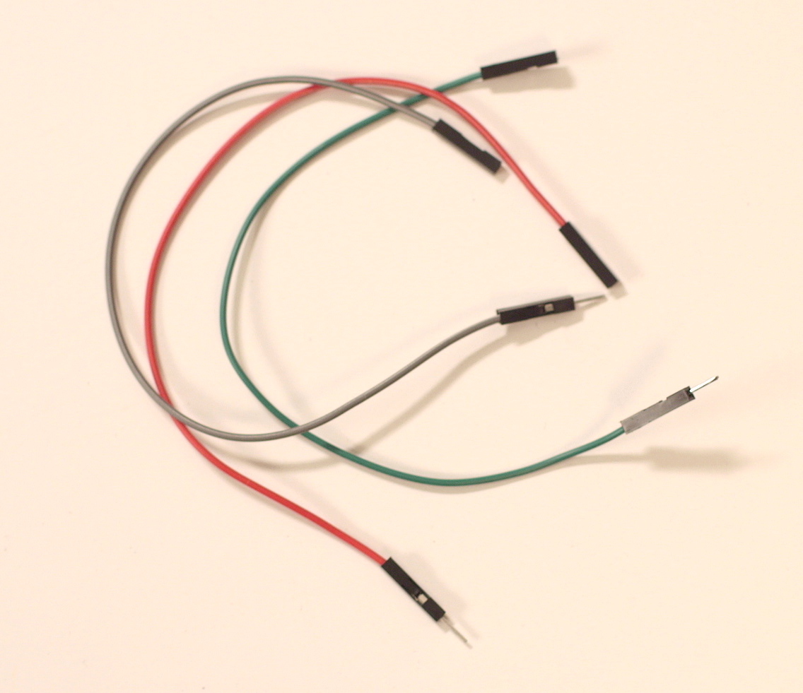
Jumper wires
Male/Female; One end connects to select GPIO pins and the other goes into the breadboard.
Additional resources:
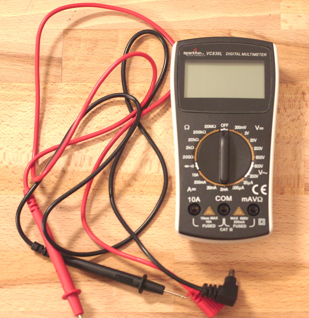
Multimeter
There are a lot options out there and you can search the internet for testimonials. Primarily, you need one that includes a voltmeter (measures voltage), ammeter (measures current) and ohmmeter (measures resistance). Your meter should include probes that you can use easily with your breadboard. Be sure to read the instructions for your meter so you are able to use it correctly. For an overview, take a look at this video from Sparkfun for some basic instructions.
Additional resources:
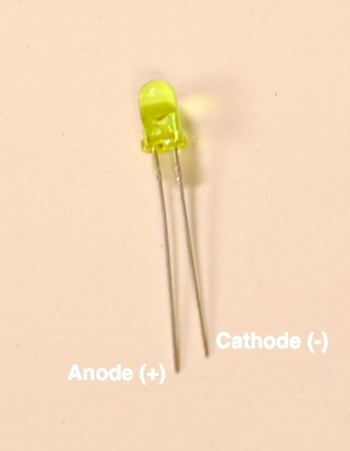
Light-Emitting Diodes (LED’s)
Recommended: basic 5mm LED color of your choice; typical forward voltage of 2.0V and a rated forward current of 20mA.
You only need one LED for the lab, but you might want to have a few available for projects, and just in case one gets blown. This can happen if the circuit has not been connected properly and too much current is put through the LED. Whatever kind you choose, be sure and also get the part number so you can look up its voltage and current requirements.
Additional resources:
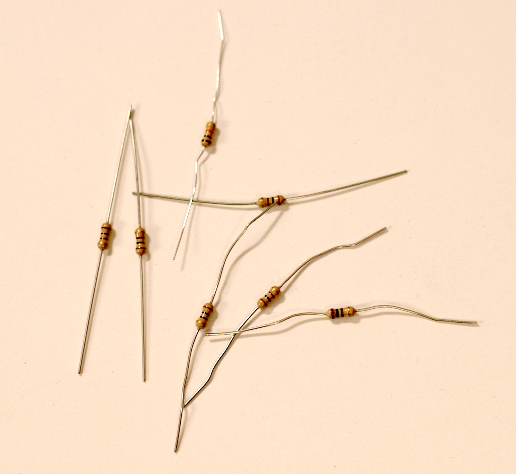
Resistors
Recommended: Assortment including 100 Ohm and 1k Ohm resistors
Resistors are needed in a circuit to divide the voltage of a circuit and to control the current flow. If we just hook an LED up to a power source it will fail because the current going through it will be too high. However, if we put a resistor in series with the LED in the circuit, we can control the value of the current and the LED will work (this will be covered later in the lab instructions). We’ll also need one for our transistor switch. The value of resistor or resistors that you need varies depending on your other specific circuit components.
Additional Resources:
Transistor
Recommended: Small signal NPN transistor such as 2N2222A or similar
For this lab, we’ll use a transistor as an electronic switch. That means we’ll hook it up to a line we can control with the software and it will in turn make the circuit turn “on” and “off” by closing and opening the circuit, just like a physical switch. The transistor circuit allows us to control the LED with a very small output signal from the system, even one that is too small to drive an LED directly.